
Automotive

ADAS calibration, static and dynamic

Why a replaced windscreen means a calibration, what a static bay actually has to guarantee, why the thrust line and not the body centreline is the reference, and how a fraction of a degree becomes a metre.

IntermediateAutomotive

Standards referencedISO 19206-3ISO 8855UN R152UN R79

A forward camera is not aimed at its bracket. It is aimed through the world, and the world is a long way off. Which is why a windscreen replacement — a job that touches no electronics at all — puts the car back on the road with its emergency braking looking somewhere slightly wrong.
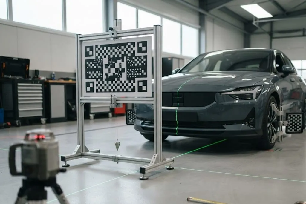
A calibration bay with a large flat black and white chequered target board held in an aluminium profile frame, a plumb bob hanging from the centre of the frame and adjustable levelling feet at the base of each leg, the frame standing squarely in front of the nose of a car, green laser lines projected along the floor and across the vehicle centreline, patterned targets clamped to the front wheels, a rotating laser level on a tripod in the foreground and a level, evenly lit workshop floor throughout.
The frame, the distance, the height and the floor. Three of the four are measured, and the fourth is assumed.

When it is required

  • Windscreen replacement or removal
  • Any sensor removed, disturbed, or replaced
  • Wheel alignment or suspension work
  • Collision repair, however light
  • A change of ride height — springs, a lift, a load-bearing modification
  • A change of tyre size

The last two catch people out, and both for the same reason. Every body-mounted sensor moves with the body. Raise the vehicle 20 mm and every forward sensor is looking 20 mm higher at the bumper and proportionally further above where it should be at range.

Why fractions of a degree matter
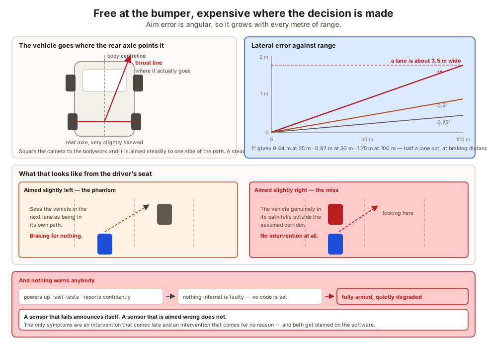
A diagram of the thrust line and the effect of angular aim error. A plan view of a vehicle shows the geometric body centreline drawn as a dashed line and the thrust line drawn separately as the direction the rear axle actually drives the vehicle, with the two diverging by a small angle, and a note that the vehicle travels where the rear axle points it rather than where the bodywork is symmetrical, so a camera aimed on the body centreline is aimed steadily to one side of the path the vehicle will take. A second panel plots lateral error against range for aim errors of a quarter, a half and one degree, showing that one degree gives about 0.44 metres at 25 metres, 0.87 metres at 50 metres and 1.75 metres at 100 metres, with a lane width marked across the chart for comparison and the observation that the error is negligible at the bumper and larger than a lane at the distance where an emergency braking decision is actually made. A third panel shows the consequence as two scenes, one where the sensor is aimed slightly left and reports the vehicle in the adjacent lane as being in its own path, and one where it is aimed slightly right and misses a vehicle that genuinely is in its path. A final panel states that a miscalibrated sensor sets no fault code because nothing about its internal operation is faulty, so the system stays fully armed and quietly degraded, and the error surfaces only as a late intervention or a phantom one.
Angular error is free at the bumper and expensive at the distance where the decision is made.

Aim error is angular, so it grows with range.

Aim error At 25 m At 50 m At 100 m
0.25° 0.11 m 0.22 m 0.44 m
0.5° 0.22 m 0.44 m 0.87 m
1° 0.44 m 0.87 m 1.75 m

A lane is roughly 3.5 m. One degree of error puts the sensor’s idea of straight ahead half a lane out at the distance where an emergency braking decision is actually being taken.

Static calibration

The vehicle is stationary and a target of known pattern is placed at a measured distance and height in front of it. The camera looks at something whose true position is known, and corrects itself.

That only works if the geometry is real, which puts requirements on the bay.

Requirement Because
A genuinely level floor A slope tilts the entire vehicle, and with it every sensor
Correct ride height — specified tyre pressures, unladen, specified fuel state A soft tyre or a loaded boot pitches the body
Measured distance and height to the target The procedure assumes both exactly
Even lighting, no glare, no strong shadow The camera must resolve the pattern cleanly
Nothing reflective or patterned behind the target A roller shutter or a striped floor confuses the pattern search

Alignment comes first

A diagram of a static calibration bay and its preconditions. A plan and side view of a bay show a vehicle positioned squarely with a patterned target frame in front of it at a specified distance and a specified height, with the floor marked as needing to be genuinely level in both directions, the measurement taken from the vehicle rather than from the wall, and the target frame square to the thrust line rather than to the building. Callouts around the vehicle list the preconditions, giving tyre pressures at the specified value, the vehicle unladen with nothing in the boot, the specified fuel state, suspension settled by rolling the vehicle rather than lowering it onto the lift, and wheel alignment completed beforehand. A lighting panel shows even diffuse illumination as acceptable, and a shaft of direct sunlight across the target, a strong shadow and a reflective roller shutter behind the target as three ways the procedure completes and is wrong. A comparison panel sets static calibration against dynamic calibration, giving static as stationary, with a measured target, repeatable, needing bay space and precise floor conditions, and dynamic as driven, learning from real lane markings and roadside structure, needing a speed band, visible markings and adequate weather and light, with a note that many vehicles require both because the static stage sets the coarse aim against a known reference and the dynamic stage refines it in the conditions the sensor will really work in.
Everything in the bay exists to make one assumption true — that the vehicle sits as it will on the road.

Wheel alignment changes the thrust line — the direction the rear axle actually drives the vehicle. Calibration establishes a relationship between where the sensor points and where the vehicle goes. Change the second one afterwards and the relationship is wrong.

This is why the thrust line, not the body centreline, is the reference. A vehicle travels where its rear axle points it, not where its bodywork happens to be symmetrical. Where the two differ, a camera squared to the body is aimed steadily to one side of the path the vehicle will take — and a steady error is worse than a random one, because it never averages out.

Dynamic calibration

The vehicle is driven, and the sensor learns its own aim from the world going past — lane markings, roadside structure, the apparent motion of stationary objects.

It needs the world to be legible:

  • A sustained speed within a specified band
  • Clear, unfaded lane markings
  • Adequate light and weather
  • Enough surrounding structure to give the algorithm something to work with

Faded paint, heavy rain, a low winter sun, or stop-start traffic will each prevent it completing. On a bad day it takes several attempts, and no amount of equipment in the workshop changes that.

What to take away

  • The camera is aimed through the world, so bracket millimetres become metres at range.
  • One degree of aim error is 1.75 m at 100 m — half a lane, at braking distance.
  • Static needs a level floor, correct ride height, a measured target and clean, even light.
  • Dynamic needs a speed band, visible markings and weather that cooperates.
  • Alignment first, always. Calibration is a relationship to the direction of travel.
  • The thrust line is the reference, not the body centreline.
  • A miscalibrated sensor sets no code, stays armed, and fails quietly. That is what makes it dangerous.

Next, what happens when prevention has run out of road — passive safety and crash engineering.

Check your understanding

10 questions. Nothing is recorded — this is just for you.

1Why does replacing a windscreen require the forward camera to be calibrated?
2How much lateral error does one degree of aim error produce at 100 m?
3Name two physical preconditions that must be satisfied before a static camera calibration.
4Why must wheel alignment be completed before calibration, not after?
5What is the thrust line, and why is it the reference rather than the body centreline?
6What does a static calibration require of the bay itself?
7What does a dynamic calibration require instead?
8Many vehicles require both procedures. Why?
9Why is a miscalibrated sensor a particularly dangerous failure?
10Why can a change of tyre size affect a calibration?

#vehicle systems#ADAS#calibration#static calibration#dynamic calibration#thrust line#wheel alignment#ride height