
Instrumentation & Control
Fire and gas detection integrity — a healthy detector in the wrong place
Coverage as a plant property rather than a device property, bump testing against calibration against function testing, the four ways a detector is disabled while reporting healthy, voting and spurious release, and what an F and G survey should produce.
Standards referencedIEC 61511IEC 60079-17NAMUR NE 107PESO
Fire and gas detection is the protection layer that acts after everything else has already failed. By the time it is relied on, containment has been lost, and the only thing standing between a release and an event is whether something saw it in time.
Which is why the question about an F and G system is never whether the detectors are working. It is whether a release from this plant, as it stands today, would reach one.
Coverage is the whole subject
Detector placement follows from an assessment: where are the credible leak sources, where does the gas go given the ventilation and the prevailing wind, where would a fire be, and what fraction of the area is covered to what standard. That assessment produces a layout, and the layout is correct on the day the plant is built.
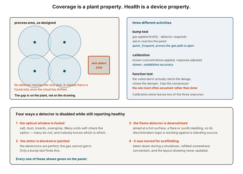
Then the plant changes. A skid is added, a pipe rack is extended, a building goes up that changes how the wind moves through the area, a wall is built to reduce noise. None of those projects carries a detection review, because none of them is a detection project.
Three different activities, routinely conflated
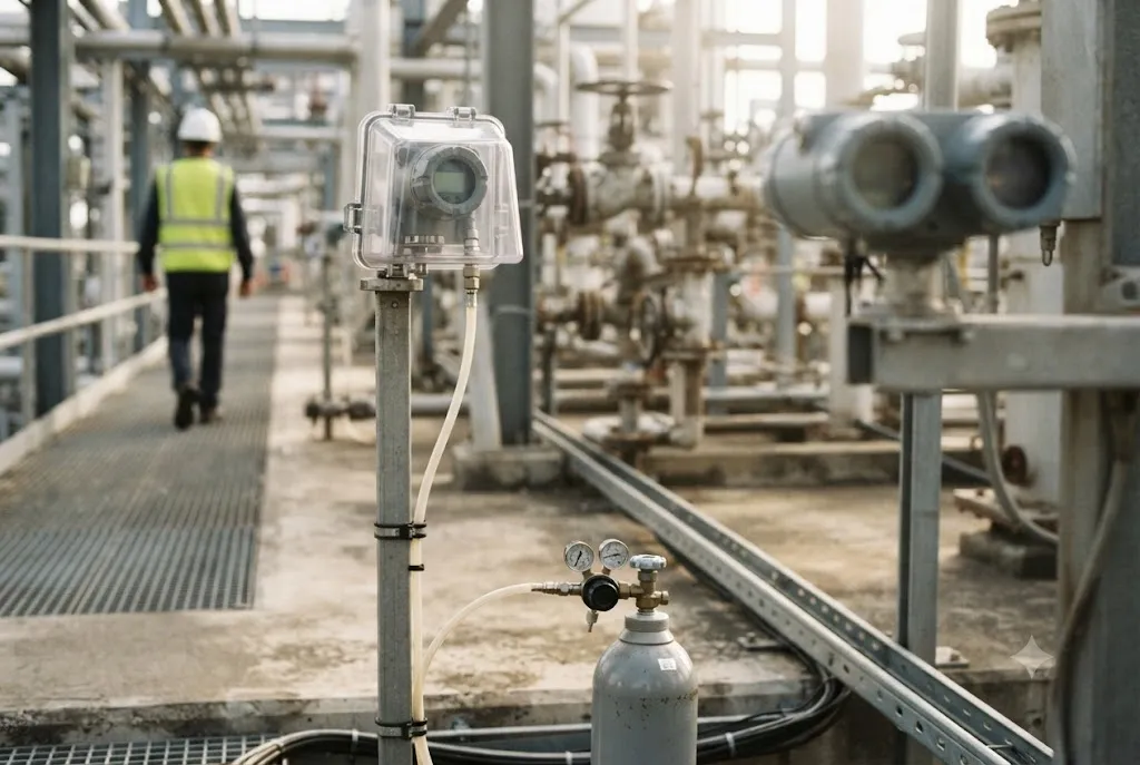
A bump test applies gas to the detector as installed and confirms that it responds and that the alarm reaches the panel. It is quick, it can be done often, and it is the only activity that proves gas can physically get to the sensing element — through the weather cap, through the sinter, past whatever has been painted over it.
A calibration applies known concentrations and adjusts the response. It establishes accuracy. It takes longer, and on many detector types it is needed much less often than a bump test.
A function test confirms the executive action: that the voted alarm actually starts the deluge, closes the damper, trips the compressor. It is the one that disrupts the plant, and therefore the one most often confirmed from the cause and effect matrix rather than by operating anything.
A plant doing only calibration has proved the middle of the three and assumed the other two.
Detector types and what each is blind to
Catalytic bead detectors oxidise the gas on a heated element. They respond to most combustibles, they need oxygen, and they are poisoned by silicones, sulphides and lead compounds — a poisoned bead reads low or zero while appearing healthy, which is why bump testing is non-negotiable on this type.
Infrared point detectors measure absorption. They do not poison and they work in an inert atmosphere, but they are blind to hydrogen, which does not absorb in the infrared, and their windows foul.
Open path infrared units measure across a beam. They cover a line rather than a point, which suits a perimeter or a long rack, and they report in different units because what they measure is concentration multiplied by path length. Misalignment, dirt and anything growing into the beam produce a slowly drifting baseline.
Acoustic detectors hear the ultrasound of a high pressure leak rather than detecting gas, so they respond immediately and independently of wind direction. They are blind to low pressure releases and they need a background noise survey, because a plant with high ambient ultrasound defeats them.
Flame detectors respond to radiation. Their field of view is a cone, so obstruction matters as much as range, and they are sensitive to what else is radiating in that cone.
No single technology covers a plant. A hydrogen service with infrared point detectors is a documented case of all four detectors in an area being blind to the gas they were installed for.
Voting, and the trade that is being made
Executive action is usually voted — typically two detectors in alarm before deluge or shutdown — because the consequence of a spurious deluge or an unwarranted compressor trip is large, and a single detector can alarm from a vehicle exhaust, a solvent container or its own fault.
That trade is legitimate, and it has a cost: a small release seen by only one detector produces an alarm on the panel and nothing else. Whether that is acceptable depends on the area, and the decision belongs in the cause and effect matrix where an operator can read it, not buried in the logic configuration.
The matrix itself deserves scrutiny. On most plants it was produced at design, modified during commissioning, and the modifications were made in the logic rather than in the document.
What an F and G survey should produce
- A current layout of every detector, verified by walking the plant, with type, range, gas and field of view.
- A coverage assessment against today’s plant, including everything added since the original design, and against the leak sources as they now are.
- A gap list with the areas not covered and what it would take to cover them.
- A maintenance routine that distinguishes bump test, calibration and function test, with separate intervals and separate records.
- A verified cause and effect matrix, compared against the logic as configured rather than as designed.
- An inhibit and bypass register for the F and G system, on the same basis as the one for trips — see proof testing and partial stroke.
Where this goes next
- Safety instrumented systems — the protection layer that acts before this one.
- Proof testing and partial stroke — testing coverage and bypass control in the same terms.
- Hazardous area basics — the classification that says where gas is expected to be.
- Alarm management — what happens to the alarm when it reaches the console.
Check your understanding
7 questions. Nothing is recorded — this is just for you.