
Automotive
CAN bus fundamentals
Why two twisted wires replaced a loom, how dominant and recessive bits let modules arbitrate without a master, what the 120 ohm terminators are for, and the handful of measurements that tell you whether a network is healthy.
Standards referencedISO 11898-1ISO 11898-2ISO 15765-2SAE J1939
A modern vehicle has forty or more modules that need to share the same handful of facts — road speed, engine torque, whether a door is open. Wiring each one to each other directly is impossible, and by the late 1980s looms were becoming the heaviest and least reliable thing on the car. CAN replaced them with two twisted wires that every module listens to.

Two wires, and why they are twisted
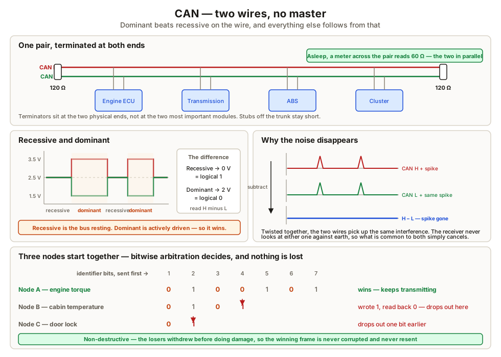
The pair is differential. Neither wire carries the signal on its own — the receiver looks at CAN high minus CAN low:
| State | CAN high | CAN low | Difference | Logical |
|---|---|---|---|---|
| Recessive | ~2.5 V | ~2.5 V | ~0 V | 1 |
| Dominant | ~3.5 V | ~1.5 V | ~2 V | 0 |
Two things fall out of this.
Noise immunity. Anything that couples into one conductor couples into the other almost equally, because they are twisted together and run side by side. Subtract them and the interference disappears. This is why a CAN pair survives being routed beside injector wiring that would destroy a single-ended analogue signal.
Dominant overrides recessive. A recessive bit is simply the bus resting. A dominant bit is actively driven. If one node drives dominant while another leaves the bus recessive, dominant wins — physically, not by agreement. That asymmetry is the foundation of everything below.
Arbitration without a master
There is no bus master and no schedule. Any node may start transmitting when the bus is idle, and two often do at the same instant. What happens then is the elegant part:
- Each transmitting node writes a bit and simultaneously reads the bus back.
- If it wrote recessive and reads back dominant, someone else is driving harder. It stops immediately and becomes a listener.
- The node that never loses a bit carries on and finishes its message.
This is non-destructive. The winning frame is not corrupted and does not need resending — the loser simply withdrew before doing any damage. Because the comparison runs across the identifier, which is sent first, the frame with the numerically lowest identifier always wins. Priority is therefore designed in when the identifiers are allocated: engine torque gets a low number, a door lock request gets a high one.
Termination
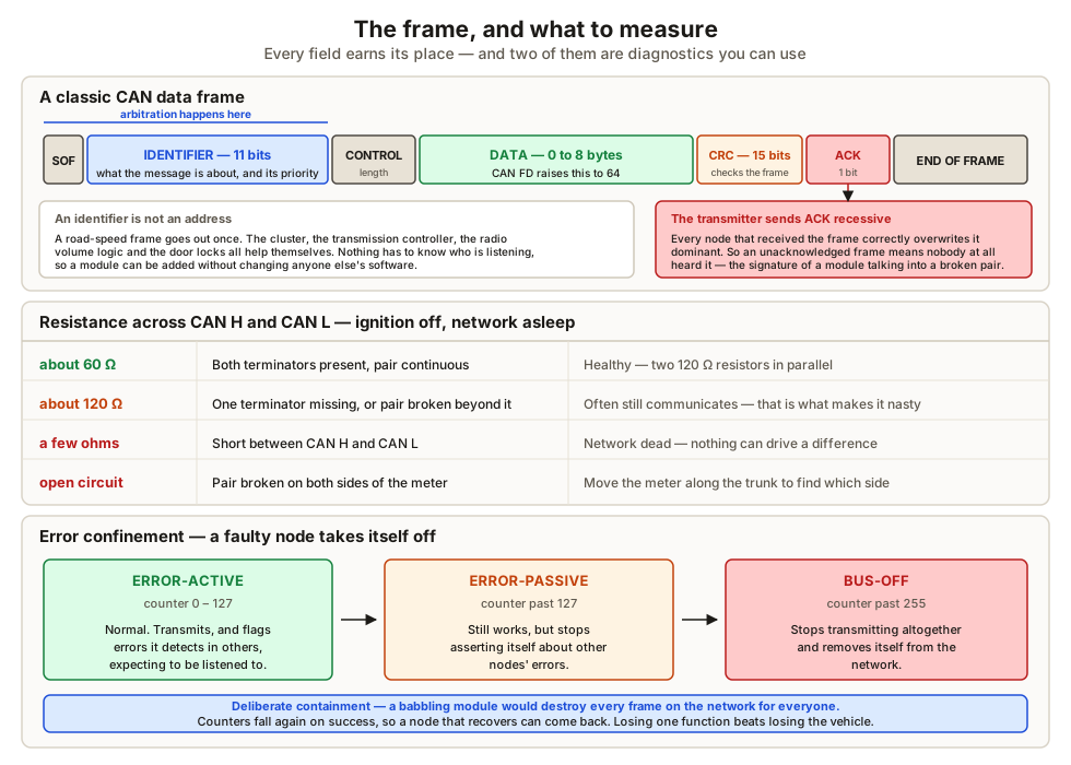
A twisted pair at 500 kbit/s is a transmission line, and an unterminated end reflects the signal back along itself. Those reflections arrive during later bits and corrupt them. The fix is a 120 Ω resistor at each physical end of the bus, matching the characteristic impedance of the cable so the energy is absorbed instead.
The diagnostic consequence is the single most useful measurement on a vehicle network. With the ignition off and the network asleep, measure resistance across CAN high and CAN low:
| Reading | Means |
|---|---|
| ~60 Ω | Both terminators present and the pair continuous — healthy |
| ~120 Ω | One terminator missing, or the pair broken beyond one of them |
| Very low | Short between CAN high and CAN low |
| Open | The pair is broken on both sides of where you are measuring |
The frame, and the acknowledge bit
A classic CAN data frame carries, in order: a start bit, the identifier (11 bits, or 29 in extended format), a control field giving the data length, up to 8 data bytes, a 15-bit CRC, an acknowledge slot, and an end-of-frame.
The acknowledge slot deserves attention. The transmitter sends it recessive and expects any node that received the frame correctly to overwrite it dominant. So the transmitter learns, within the same frame, whether anybody at all heard it. An unacknowledged frame is the classic signature of a module transmitting into a broken pair — and it is why a module can set a communication fault about itself.
Error confinement
Every node keeps a transmit and a receive error counter. They rise on failure and fall on success.
- Error-active — normal. The node flags errors it detects and expects to be listened to.
- Error-passive — past 127. The node still works but flags errors much less assertively.
- Bus-off — past 255. The node stops transmitting altogether and removes itself.
This is deliberate containment. A faulty module that transmits nonsense continuously would destroy every frame on the network for everyone, so the protocol makes it quarantine itself. Losing one function beats losing the vehicle.
Speeds, and what came next
High-speed CAN (ISO 11898-2) runs at 500 kbit/s on powertrain networks and 125–250 kbit/s on comfort networks. Low-speed fault-tolerant CAN runs slower and keeps working with one wire down by design.
CAN FD — flexible data rate — keeps the arbitration phase at the original speed, so priority still works exactly as above, then switches to a higher rate for the data field and allows up to 64 bytes instead of 8. Keeping the arbitration phase compatible is precisely what allowed it to be adopted gradually rather than all at once.
What to take away
- The pair is differential and twisted, so induced noise cancels at the receiver.
- Dominant beats recessive on the wire. That one asymmetry gives non-destructive arbitration.
- The lowest identifier wins, and an identifier names content, not a destination.
- 120 Ω at each end; 60 Ω across the pair with the network asleep proves both.
- Every receiver drives the acknowledge bit, so a transmitter knows when nobody heard it.
- Bus-off is a node removing itself so it cannot jam the network.
- CAN FD raises the payload to 64 bytes and speeds up only the data phase.
CAN is not the only network on a vehicle, and it is deliberately not used for everything — see LIN, FlexRay, Ethernet and ECU architecture.
Check your understanding
10 questions. Nothing is recorded — this is just for you.