
Automotive
Actuators and PWM control
How a control module makes something happen — solenoids and their inductive kick, why pulse width modulation replaced the resistor, duty cycle as a command, H-bridges for reversible motors, and what closed-loop position control adds.
A sensor lets the module know. An actuator lets it act. The interesting part is that a microcontroller can only really do one thing to a wire — connect it or not — and almost every form of modulated control on a vehicle is built out of that single ability used cleverly.

The solenoid, and the spike nobody expects
Most actuators start as a solenoid — a coil round a movable iron armature. Energise it and the armature is pulled in against a spring; de-energise and the spring returns it. Injectors, purge valves, transmission shift valves and starter solenoids are all this.
The part that catches people out is switching off. An inductor resists a change in current, so interrupting the current produces a reverse voltage spike that can reach several hundred volts. Left alone, it destroys the switching transistor. Two answers are used:
- A flyback diode across the winding, reverse biased in normal use, which conducts when the polarity reverses and lets the energy circulate until it decays. Cheap and effective.
- A clamp at a controlled higher voltage — typically built into the driver — where the release needs to be fast. The flyback diode slows the collapse of the field and therefore the return of the armature, and for an injector that closes thousands of times a minute, that matters.
Pulse width modulation
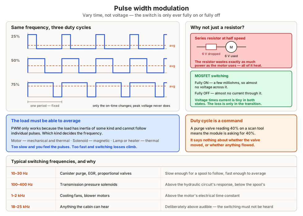
Instead of varying voltage, vary time. The switch runs at a fixed frequency and what changes is the fraction of each cycle it spends on — the duty cycle. A load with inertia of some kind responds to the average:
- A blower motor has mechanical and thermal inertia, so it sees 50% duty as roughly half speed.
- A solenoid has magnetic inertia, so a partially energised proportional valve holds a partial position.
- A heater or lamp has thermal inertia, so it sees an average power.
The efficiency argument is the whole reason this displaced the older resistor pack. A resistor dropping half the voltage at the same current wastes exactly as much power as the load uses, and turns it into heat that then has to go somewhere. A MOSFET that is fully on has milliohms of resistance, and fully off passes essentially nothing, so in both states the power lost in the switch is negligible. The only real loss is in the transitions between them, which is why switching frequency is chosen carefully rather than simply raised.
| Typical PWM frequency | Where | Why that figure |
|---|---|---|
| 10–30 Hz | Canister purge, EGR, some proportional valves | Slow enough for a spool to follow, fast enough to average |
| 100–400 Hz | Transmission pressure solenoids | Above the hydraulic circuit’s response, below the spool’s |
| 1–2 kHz | Cooling fans, blower motors | Above the motor’s electrical time constant |
| 18–25 kHz | Anything near the cabin | Deliberately above audible, so the switching cannot be heard |
Driving a motor in both directions
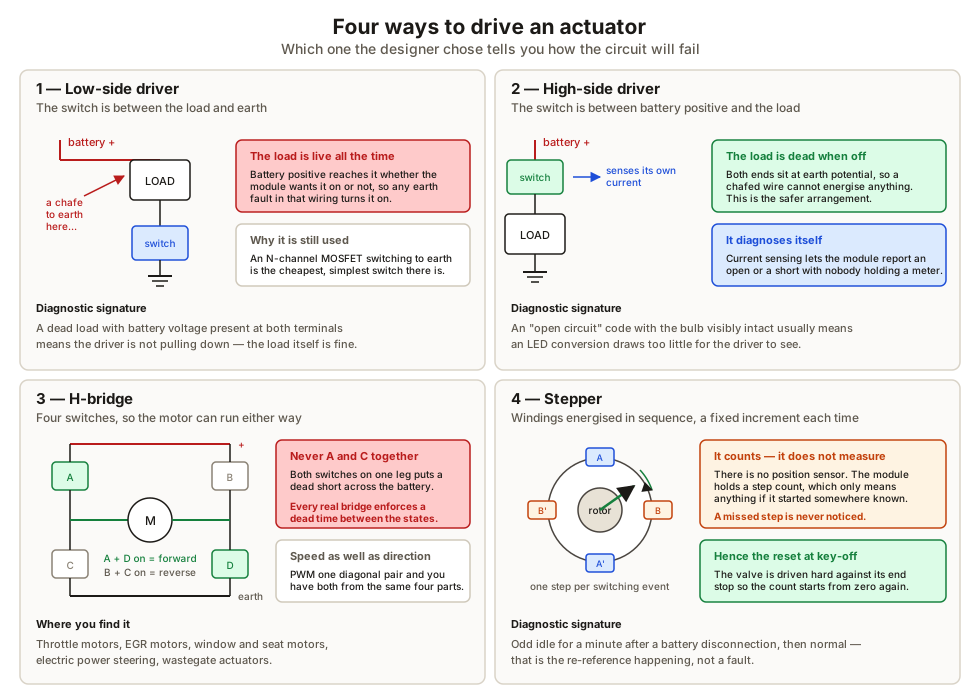
Low-side driver. The switch is between the load and earth, so the load sits permanently at battery positive. Simple, cheap, and the reason a chafed wire to earth energises the load.
High-side driver. The switch is between battery positive and the load, so when it is off the load is dead. Modern ones sense their own current and report open circuits and shorts on the bus, which is how a module sets an “open circuit, cooling fan relay” code with nobody holding a meter.
H-bridge. Four switches arranged so either end of the motor can go to supply or to earth. One diagonal pair drives forward, the other reverse, and PWM on top of that gives speed. Turning on both switches on the same leg at once puts a dead short across the battery, so every practical H-bridge enforces a dead time between the two states.
Stepper. Two windings energised in sequence to advance the rotor a fixed increment per step. Inherently open loop on position — the module counts steps from a reference, which is only meaningful if it started from somewhere known. That is why an idle air control valve is driven hard against its end stop at key-off, and why idle behaviour is strange after a battery disconnection until it has reset.
Closed loop, and the difference it makes
An open-loop command assumes the actuator behaves as modelled. It does not, quite — friction, wear, temperature and supply voltage all move the result. A closed-loop actuator carries a sensor on its output and the module drives the error between commanded and actual towards zero.
An electronic throttle is the clearest example. The module commands a plate angle; the dual-track position sensor reports the angle actually reached; the driver corrects until they match. Consequences worth knowing:
- A sticking plate sets a fault rather than quietly moving less than asked.
- The motor has to work against the return spring in both directions, because that spring defines the safe state — a small default opening that lets the engine idle and the vehicle limp if the drive fails.
- After a battery disconnection the module has to relearn the closed stop, which is why some vehicles idle badly for a minute and then settle.
What to take away
- Switching a solenoid off is the dangerous moment; a flyback diode or a controlled clamp handles the spike, and the choice affects how fast the armature releases.
- PWM varies time, not voltage. Efficiency comes from the switch being fully on or fully off.
- Duty cycle on a scan tool is a command. It is not evidence that anything moved.
- High-side drivers leave the load dead when off and can diagnose themselves; low-side drivers cannot.
- An H-bridge gives reversal, and needs dead time to avoid shorting the supply through one leg.
- Steppers count, they do not measure — hence the re-reference at key-off.
- Closed loop means a sensor on the output. It is what turns a command into a guarantee, and what turns a mechanical problem into a fault code.
Sensors and actuators between them produce far more traffic than individual wires can carry, which is where the CAN bus comes in.
Check your understanding
10 questions. Nothing is recorded — this is just for you.