Civil & Structural
Foundations — how the soil report decides what you build
Safe bearing capacity, shallow versus deep foundations, why vibrating equipment needs a different design, and what the civil engineer needs from the other disciplines.
Every structure in a plant eventually transfers its weight into the ground. The civil engineer’s job is to do that without the structure sinking, tilting or shaking itself apart. Nearly all of it is decided by one document.
It starts with the soil report
Before a single foundation is designed, a geotechnical investigation is done: boreholes across the plot, samples taken at intervals, standard penetration tests, laboratory testing of strength and consolidation, and a check on groundwater level and chemistry.
The report gives the civil engineer:
- Safe bearing capacity (SBC) in kN/m², at stated depths — the pressure the soil can carry without shear failure or excessive settlement.
- Soil profile — what layers exist, how thick, and how strong.
- Groundwater level, which affects buoyancy, excavation and construction method.
- Chemical aggressiveness — sulphate and chloride content, which sets the cement type and the concrete cover.
- Settlement predictions — how much the ground will compress, and over what period.
Shallow or deep
The first and largest decision is shallow versus deep, and it is driven entirely by whether competent soil exists near the surface.
| Isolated / pad footing | Shallow | 1.5 – 3 | Good bearing soil near the surface and columns are well separated | Pipe rack columns, single equipment supports, small structures |
|---|---|---|---|---|
| Combined footing | Shallow | 1.5 – 3 | Two columns are too close for separate pads, or one is at a boundary | Closely spaced structural columns |
| Strip footing | Shallow | 1 – 2.5 | Load is continuous along a line rather than at points | Walls, long equipment plinths, pipe sleeper rows |
| Raft / mat | Shallow | 2 – 4 | Soil is weak or variable and individual footings would overlap anyway | Compressor houses, tank bottoms, control buildings on poor soil |
| Octagonal / annular | Shallow | 2 – 4 | The equipment is round and carries significant wind or seismic overturning | Vertical vessels, columns, stacks |
| Bored cast-in-situ pile | Deep | 10 – 40 | Competent strata is deep, or settlement must be tightly controlled | Heavy rotating equipment, large vessels, tanks on soft ground |
| Driven precast pile | Deep | 10 – 30 | Deep soft soil and the site tolerates driving noise and vibration | Jetty structures, plant on reclaimed or marshy land |
| Pile cap on pile group | Deep | Cap 1.5 – 3 over piles | A single pile cannot take the column load or the moment | Pipe rack and structural columns on piled areas |
No rows match that filter.
The choice is driven by the geotechnical report, not by preference. If the safe bearing capacity at a shallow depth cannot carry the load without excessive settlement, you go deep — and the cost difference between shallow and piled foundations across a whole plot is very large.
The sizing arithmetic
For a shallow footing the starting calculation is simple:
Required area = Total load / Safe bearing capacityA column carrying 900 kN on soil with SBC 150 kN/m² needs 900/150 = 6 m², so about 2.45 m square. Then the design gets properly underway: self-weight of the footing, uplift from wind, overturning moments, eccentric loading, and the bending and shear checks that set the thickness and reinforcement.
Foundations in a process plant
Plant foundations are not building foundations. Some recurring types:
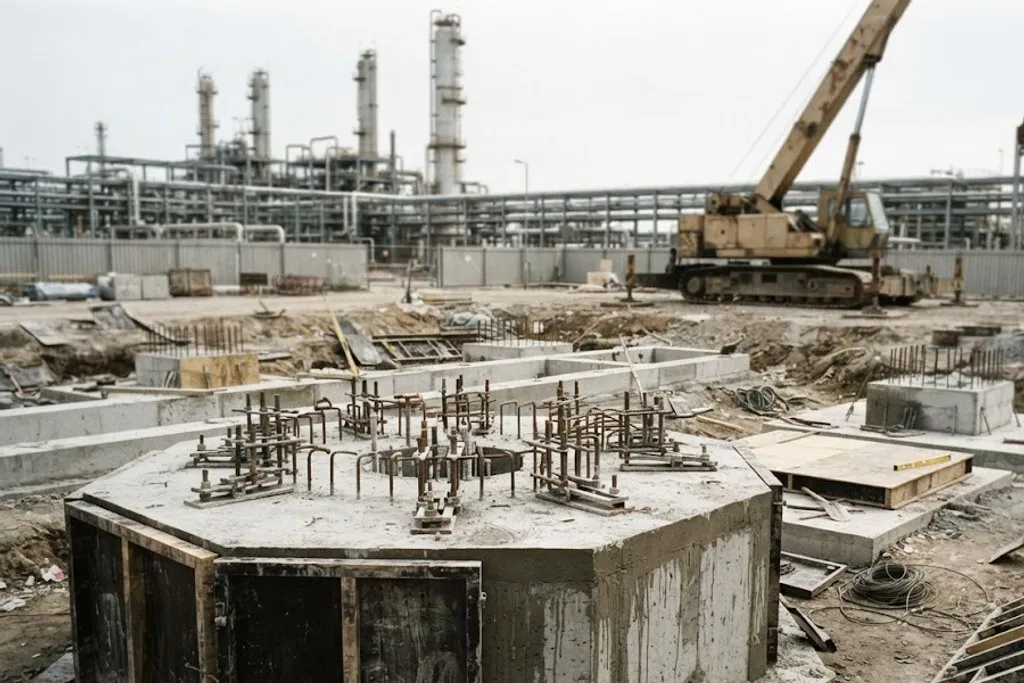
Equipment plinths. A raised concrete block carrying a pump, compressor or skid. Raised so the base is above the paving and drains, and so grout can be packed under the baseplate. Holding-down bolts are cast in with pockets or sleeves that allow a little adjustment, because the equipment will not arrive perfectly to drawing.
Vertical vessel foundations. Usually octagonal or circular. The governing case is rarely the vessel’s weight — it is overturning from wind or seismic load on a tall slender object. The foundation is sized so it cannot lift or tip, which often means a base much wider than the weight alone would need.
Pipe rack foundations. Isolated footings at regular bays, carrying the rack columns. The loads are unglamorous but numerous: dead weight of pipes, contents, insulation, plus thermal expansion forces and anchor loads where a line is fixed.
Tank foundations. Usually a compacted pad with a ring beam rather than a full slab. Large tanks settle measurably when first filled, which is precisely why a hydrotest is done before the tank goes into service.
Machine foundations. The genuinely specialised case, covered below.
Vibrating machines are a different problem
A pump, compressor or turbine imposes cyclic forces. Design the foundation only for the static weight and you may build something whose natural frequency sits close to the machine’s running speed — and then resonance amplifies the vibration until the grout cracks, the bolts loosen and the bearings fail.
Machine foundation design therefore tunes mass and stiffness so the natural frequency is well away from the operating frequency. Rules of thumb that appear in most specifications:
- The block mass is typically 2–3 times the machine mass for rotating equipment, and 3–5 times for reciprocating equipment.
- The natural frequency should differ from the operating frequency by at least 20–30%.
- The block is usually isolated from the surrounding paving so vibration does not travel.
IS 2974 and the equivalent international guides set out the method. The machine vendor must supply the unbalanced forces and frequencies — without them, the foundation cannot be designed, only guessed.
Concrete, in the terms you will meet
Grade is the characteristic compressive strength at 28 days: M25 means 25 N/mm² in Indian practice (IS 456); C25/30 in European practice gives cylinder and cube strengths. Plant structural concrete is usually M25 to M40.
Cover is the concrete thickness between the outer face and the nearest reinforcement. It protects the steel from corrosion and is increased in aggressive or marine environments — typically 40 mm for foundations in normal soil, 50–75 mm where sulphates or chlorides are present.
Reinforcement is deformed steel bar, specified by grade (Fe500, or Grade 60) and diameter. It carries the tension that concrete cannot.
Lean concrete is a weak blinding layer, usually M10, poured on the excavated soil to give a clean level working surface and to stop the structural pour losing water into the ground.
What civil needs from everyone else
Foundation design cannot start until the other disciplines supply their loads. This is the most common source of civil rework on a project:
- Mechanical — equipment weights (empty, operating and hydrotest), centre of gravity, nozzle loads, and the certified holding-down bolt layout.
- Piping — pipe rack loads, anchor and guide forces, thermal expansion effects.
- Electrical — transformer and switchgear weights, cable trench and duct bank routes, earthing pit locations.
- Instrumentation — analyser house and rack locations, and any cable trench that clashes with a footing.
What to take away
- Everything starts from the geotechnical report. Design without one and you are guessing.
- Required area = load / SBC gets you started; settlement, overturning and differential movement usually govern the final design.
- Shallow foundations when competent soil is near the surface; piles when it is not.
- Vibrating machinery needs mass and stiffness tuned away from resonance, using vendor force data.
- Civil works last on paper and first on site — which means it needs everyone else’s loads early.
Check your understanding
10 questions. Nothing is recorded — this is just for you.